For those looking to solve issues with their air compressor, an electrical pressure switch diagram can be a great aid. However, before you can put the schematic to practical use, you need to be aware of two key facts: the purpose of each distinctive color on the wiring diagram and the meaning of each numerical indicator.
The pressure switch wiring diagram for an air compressor indicates which colors carry certain signals. Usually, the black wire serves as the ground wire, the red wire is the power wire, the white wire stands for the neutral line, and green carries the safety connection.
The pressure switch wiring diagram for an air compressor can reveal a wealth of knowledge. The number one painted on the wires could indicate the power source, while the number two may denote the ground wire. The third might signify the neutral wire, and finally, the fourth number could stand for the safety wire.
Having established the various colors illustrated on the pressure switch wiring diagram air compressor, you now require knowledge on utilizing it. Locate the power wire initially, which can be identified though its black hue. Having located the power wire, connect it to the black wire of the pressure switch to effectively employ it.
Once the pressure switch’s white wire has been located, the ground wire must then be found. This particular ground wire shall be recognised by its white shade. The duty at hand is connecting this ground wire to its white pair on the pressure switch.
To secure the mechanism, you must seek its essential safeguard – the green safety wire. Locate it and attach it to the corresponding green wire of the pressure switch.
Knowing how the pressure switch wiring diagram air compressor works is important, but it is useless if you cannot decipher it. To get started, you must locate the power wire, which can easily be found by its black color. Once apprehended, this power wire must be attached to the black wire on the pressure switch.
For the purpose of grounding, discover the white wire – this is the ground wire. Afterward, attach this wire to the also-white cord found with the pressure switch.
To ensure safety when dealing with electrical pressure, the crucial part is identifying and connecting the green wire labelled ‘safety wire’ to its companion on the pressure switch.
For your pressure switch wiring diagram air compressor to function effectively, troubleshooting it is an essential step. Begin by locating the power wire, identifiable by the black cord. Connect the power wire to the black wire on the pressure switch to complete the setup.
To continue, aim to locate the ground wire which is plainly marked by its white color. Once you’ve identified it, attach the white wire of the ground wire to the pressure switch for completion.
To continue, the next step is to locate the safety wire – which is unmistakably green in color. Afterwards, simply link the safety wire to the green wire located at the pressure switch.
Once you have identified the black power wire in the pressure switch wiring diagram of your air compressor, it’s time to put it to use. First, you need to attach the black power wire to the corresponding black pressure switch wire. Once this is complete, you can move on to the next step in the process.
After that, you ought to locate the ground wire, which will be the white one. Once you’ve pinpointed it, simply link it to the white wire on the pressure switch.
After the searching is done, you will locate the green safety wire. This must be linked to the pressure switch’s corresponding green wire to complete the installation process.
In order to successfully use a pressure switch wiring diagram for an air compressor, the power wire needs to be identified. Typically this will be indicated in the diagram as a black wire. Once the wire has been identified, connecting it to the black wire on the pressure switch is essential to move forward with the entire process.
With your next step, you must locate the ground wire; it should be the white one. Once addressed, you must link the white wire on the pressure switch to its matching counterpart.
In order to complete the circuit, you must locate the safety wire which is green. Once identified, attach it to the green wire present on the pressure switch to power up the system.
Post time: 2023-06-24Related Product
Warning: Use of undefined constant rand - assumed 'rand' (this will throw an Error in a future version of PHP) in /www/wwwroot/www.sunritamachinery.com/wp-content/themes/msk5/single.php on line 69

TPB90 Air Breaker Pavement Paving Breaker
Product introduction: TPB-90 crusher adopts the mature technology of TOKU Group, Is compressed air as the power of the crushing tool, can efficiently complete the reinforced concre […]
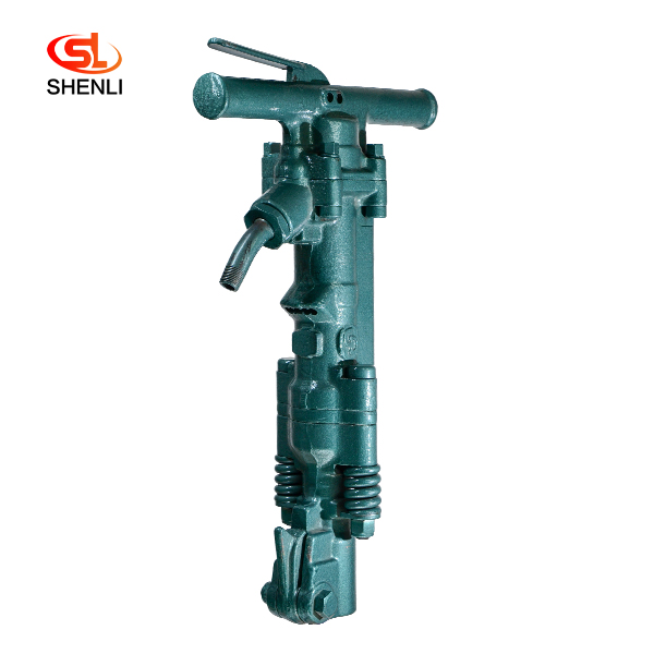
B47 Pneumatic Pick Air Shovel Cement Crusher Pneumatic Chipping Hammer
Product Description: B47 crusher adopts the mature technology of American Gardner Denver Pneumatic Group Company,It is a crushing tool powered by compressed air, which can finish r […]
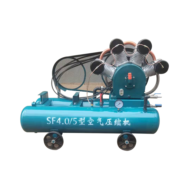
20KW Mining Diesel Piston Air Compressor SF4.0-5
Advantages Small in size,light in weight, easy to move Top material and superior technology Simple structure, high efficiency, good performance, and low price Adopt the most popula […]
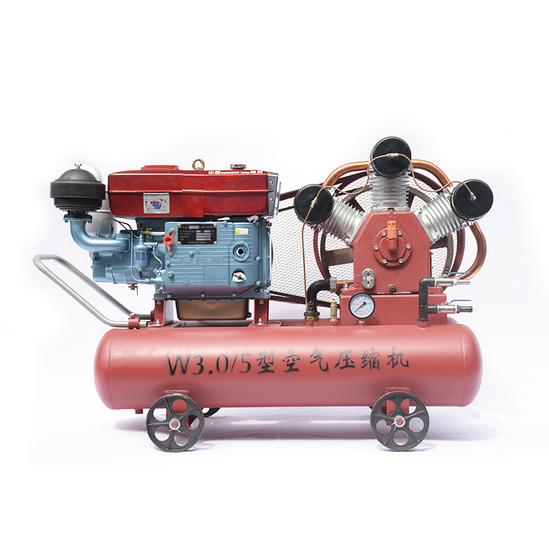
15kW Mining Diesel Piston Air Compressor W3.0-5
Diesel Portable Piston Air Compressor Mobile for Jack Hammer / Mining 1.Simple structure,light weight,easy to move . 2.Easy operating and maintenance. 3.High quality air delivery. […]

TPB6 Air Concrete Breaker Pneumatic Pick
Product introduction: TPB-60 crusher adopts the mature technology of TOKU Group, Is compressed air as the power of the crushing tool, can efficiently complete the reinforced concre […]
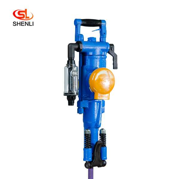
YT28 Pusher Leg Rock Drill
Short Description: The YT28 air-leg rock drill is a kind of high-efficiency, energy-saving and environmentally friendly rock drilling equipment. Compared with similar pneumatic pro […]
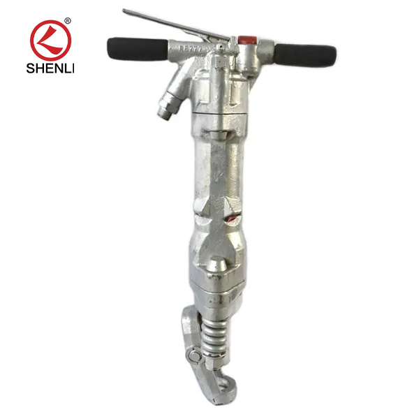
RB777 Pneumatic Pick Air Shovel Cement Crusher Pneumatic Chipping Hammer
Product description: RB777 pneumatic picks are used to build roads, install works of broken concrete and other hardens Hard object tools, the machine structure is simple, high effi […]
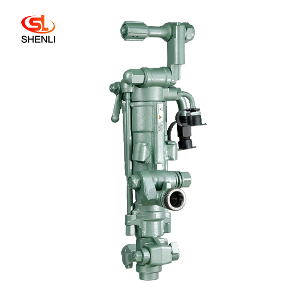
S250 Air Leg Pneumatic Rock Drill Pusher Leg Rock Drill
Product description: (S250 jackleg Drill) has been the preferred choice of miners who demand high performance, superior control and lasting reliability. the S250 jackleg allows ope […]
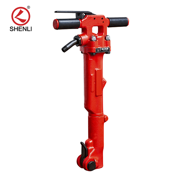
TPB40 Air Breaker Pavement Paving Breaker
Product introduction: Tpb-40 pneumatic crushing pick is a tool powered by compressed air.The compressed air is distributed to both ends of the cylinder block in turn to make the ha […]