An air compressor is a vital part of many job sites and even the home garage. It can provide the pneumatic force necessary to power certain tools or pump up tires for vehicles. To ensure that this device runs safely and efficiently, it is critical to follow a dependable wiring diagram.
Before getting into the nitty-gritty of air compressor wiring diagrams, we must first familiarize ourselves with the fundamental parts of an air compressor.
An air compressor essentially has five fundamental components- a motor, compressor pump, tank, pressure switch, and safety valves. To create compressed air, the motor propels the pump which compresses the air and stores it in the tank. The pressure switch tracks the tank pressure and operates the motor intermittently in order to sustain a secure operating pressure level. Additionally, the safety valves are implemented to bring down the pressure in case it surpasses the maximum level, shielding the tank from potential busting.
Let’s dig into the intricacies of air compressor wiring diagrams.
An air compressor’s wiring diagram frequently illustrates the integration of several components as well as the relations between them. These parts usually consist of:
A standard, 120-volt and 15-amp circuit is essential for providing electrical power to the motor and pressure switch in a power supply system.
The motor is connected to the power source via a switch designed to turn it on and off, which also features a thermal overload mode for safeguarding against any potentially excessive heatwave.
The pressure switch maintains a level of safety for the motor and tank during operation by powering up and powering down the motor in response to the pressure levels within the tank. Wiring connects this switch to both the motor and the tank, keeping the system running smoothly while ensuring that safe operating pressure remains sustained.
The tank is a cornerstone of the pneumatics set-up; it’s connected to both the motor and pressure switch for a reliable source of compressed air. With its presence, a range of tasks can now be accomplished with ease – be it airbrushing, powering up pneumatic tools, or giving life to sluggish tires.
The integrated safety valves in tanks are programmed to kick in when pressure gets dangerously high, averting a possible rupture and releasing pressure until the danger dissipates.
When connecting up an air compressor, it is paramount that you adhere to the manufacturer’s manual and local electrical regulations. To guarantee a safe and dependable installation, consider the following advice:
To create an optimal setup, it’s important to understand the importance of gauge wire in relation to the components of the motor. In general, a beefier wire gauge should be employed for this particular piece than for the rest of the elements.
To ensure electrical current flows smoothly and safely, double-check that all wiring is securely fastened and insulated appropriately.
Connect wires tidily by twisting together capped with wire nuts and bound with electrical tape to provide a secure joint.
To protect against electric shock and damage, it is essential to connect firmly the motor and metal components of the air compressor to the ground.
An air compressor wiring diagram is essential to the flawless functioning of an air compressor system. With the right comprehension of the different components and connections associated with an air compressor, coupled with prudent wiring techniques and safety protocols, you can guarantee optimum performance from your air compressor without unintended consequences.
Post time: 2023-05-30Related Product
Warning: Use of undefined constant rand - assumed 'rand' (this will throw an Error in a future version of PHP) in /www/wwwroot/www.sunritamachinery.com/wp-content/themes/msk5/single.php on line 69

Rock Drill Button Bit
Product introduction: Taper bits, especially Tapered button bits are the most popular tapered drill bits with a wide selection of head diameters from 26mm to 48mm. With carbide but […]
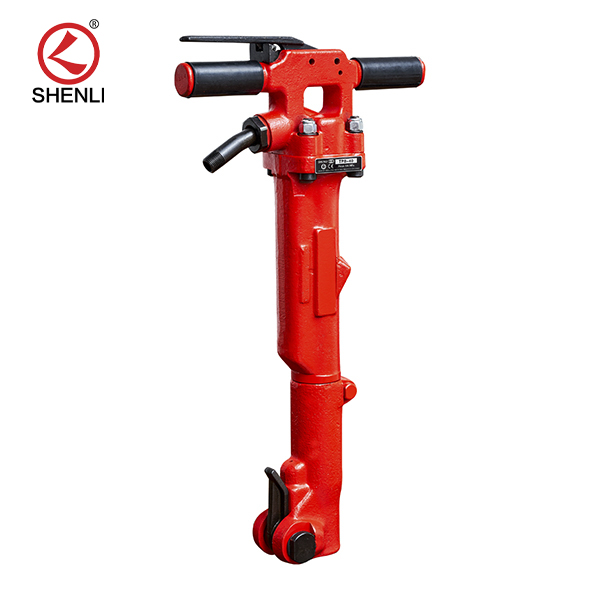
TPB40 Air Breaker Pavement Paving Breaker
Product introduction: Tpb-40 pneumatic crushing pick is a tool powered by compressed air.The compressed air is distributed to both ends of the cylinder block in turn to make the ha […]
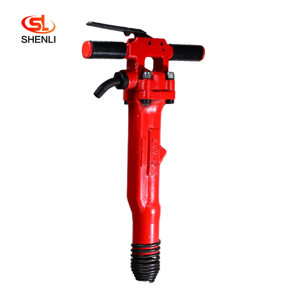
B37 Pneumatic Pick Air Shovel Cement Crusher Pneumatic Chipping Hammer
Product Description: B37 pneumatic crushing pick is a tool powered by compressed air. The compression the air is distributed to the two ends of the cylinder block in turn, so that […]
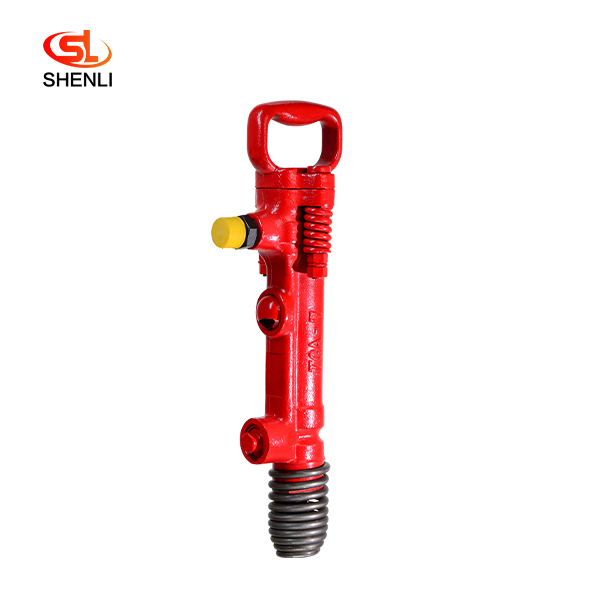
TCA7(G7)Pneumatic Pick Air Shovel Cement Crusher Pneumatic Chipping Hammer
Product introduction: Adopted Japan’s Toku technology, the air picks with proven forging technology are durable, lightweight and good performance, and easy to operate. Mainly […]
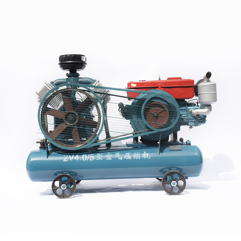
20KW Mining Diesel Piston Air Compressor 2V4.0-5
Double Air Tank Diesel Portable Best-Selling Engine Oil Piston Air Compressor are mainly used to supply stable and clean compressed air to the pneumatic tools and keep them working […]
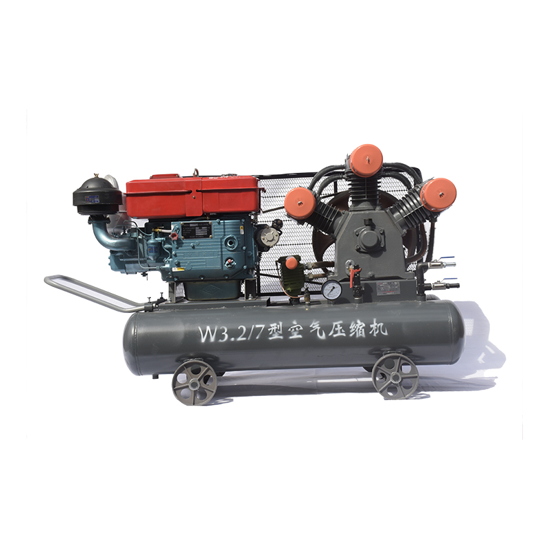
20KW Mining Diesel Piston Air Compressor W3.2-7
Advantages Small in size,light in weight, easy to move Top material and superior technology Simple structure, high efficiency, good performance, and low price Adopt the most popula […]

TPB6 Air Concrete Breaker Pneumatic Pick
Product introduction: TPB-60 crusher adopts the mature technology of TOKU Group, Is compressed air as the power of the crushing tool, can efficiently complete the reinforced concre […]
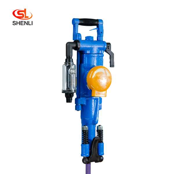
YT28 Pusher Leg Rock Drill
Short Description: The YT28 air-leg rock drill is a kind of high-efficiency, energy-saving and environmentally friendly rock drilling equipment. Compared with similar pneumatic pro […]
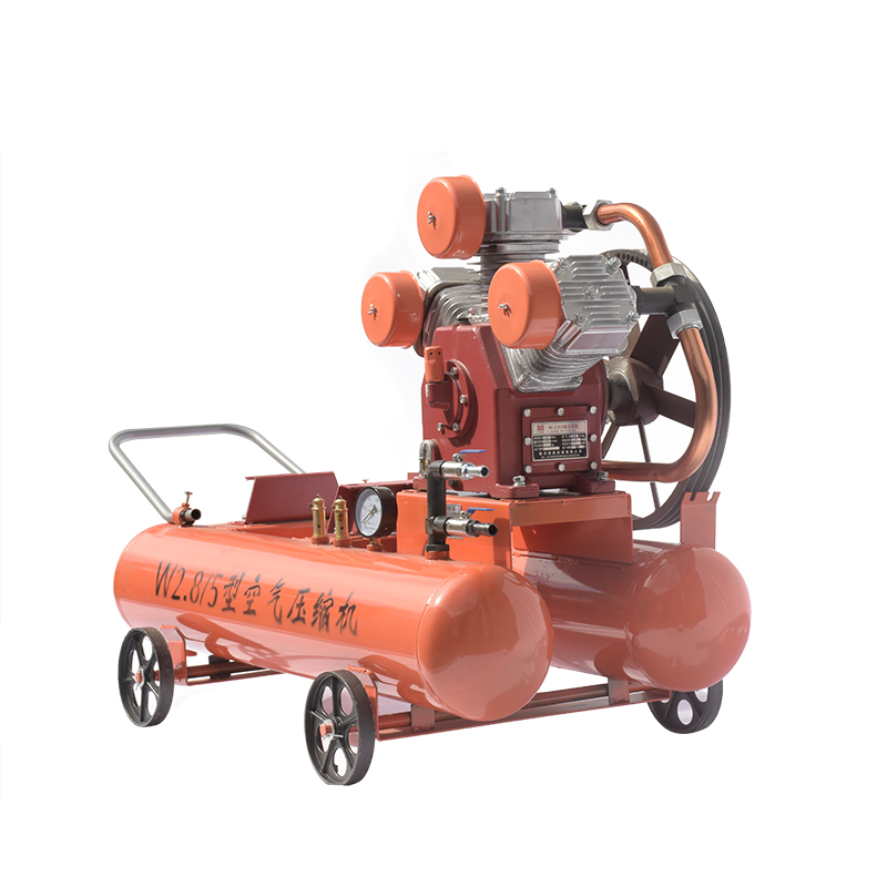
15KW Mining Diesel Piston Air Compressor W2.8-5
Diesel Portable Piston Air Compressor Mobile for Jack Hammer / Mining 1.Simple structure,light weight,easy to move . 2.Easy operating and maintenance. 3.High quality air delivery. […]